25+ Best Looking For Engineering Drawing Symbols Diameter
Engineering drawing symbols diameter Engineering drawing abbreviations and symbols are used to communicate and detail the characteristics of an engineering drawingthis list includes abbreviations common to the vocabulary of people who work with engineering drawings in the manufacture and inspection of parts and assemblies. Engineering drawings are the industrys means of communicating.


Best For Engineering Drawing Symbols Diameter

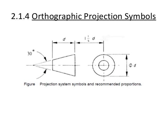
Engineering drawing symbols diameter. Basic symbols used in engineering drawings by kelly curran glenn sokolowski. The first tool in your engineering drawing toolbox is the drawing view. This mechanical engineering diagram was created in conceptdraw diagram software using the mechanical drawing symbols from the libraries of mechanical engineering solution and shows the schemes of hydraulic circuits.
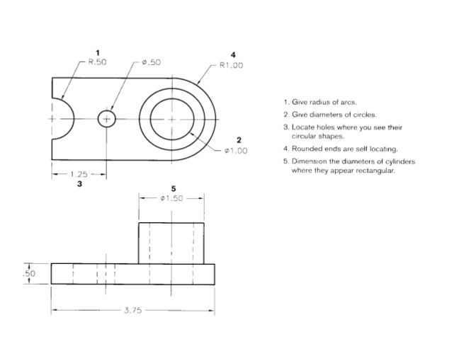
Learners examine the drawing symbols used for counterbore countersink spotface radius diameter and depth. O interpret information on detail drawings of engineering components. Ansi and iso geometric tolerancing symbols.
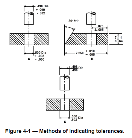
There are 7 aspects of the gdt methodology that we will discuss these include. Views dimensions tolerances symbols datums feature control frames title blocks. Block of an engineering drawing.
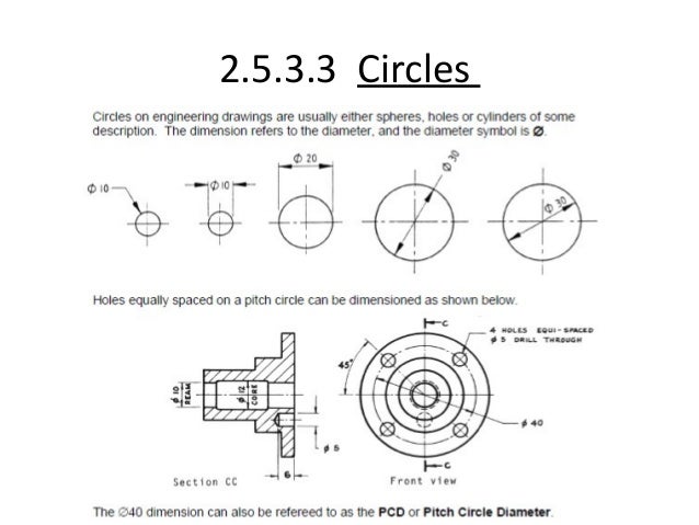
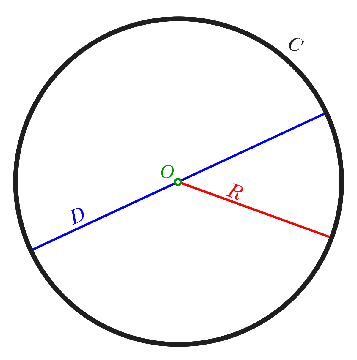
These are american society of mechanical engineers asme y145m 2009 gdt geometric dimensioning and tolerancing and international organization for standardization isotc 213 gps geometrical product specification and isotc 10 technical product. That in the real world people measure diameters rather than radii is one of the reasons that i suggest that the tauists people who suggest we ought use 634 62833 rather than 317 31416 as the circle meas. O is the diameter of a circle.
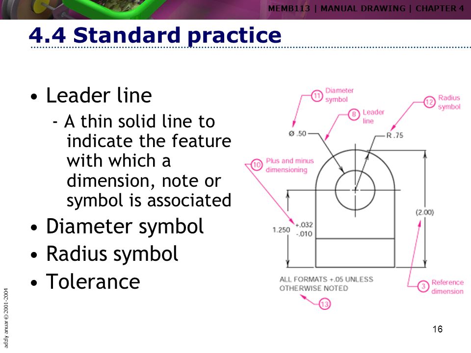
There are several standards available worldwide to describe the symbols and the rules. Section 61 drafting manual page 2 dimensioning and tolerancing august 1993 symbols update 47 24 depth a downward pointing arrow is used for the depth symbol and it is placed in front of the depth value in such applications as for counterbore and hole depths. The ability to read and understand information contained on drawings is essential to perform most engineering related jobs.
Basic and common symbols recognition purpose this section aims to enable the student to extend their knowledge of drawing interpretation from engineering drawings produced to as1100 standard. In unicode it is defined as u2300 diameter sign html 8960. Mechanical engineering diagram hydraulic circuits.
Objectives at the end of this section you should be able to. Eo 14 state the purpose of the notes and legend section of an engineering drawing. An experienced user spent 25 minutes creating this sample.
See also slashed zero. The diameter symbol is distinct from the empty set symbol from an uppercase phi f and from the nordic vowel o. It is similar in size and design to o the latin small letter o with stroke.


Don't forget to bookmark using Ctrl + D (PC) or Command + D (macos). If you are using mobile phone, you could also use menu drawer from browser. Whether it's Windows, Mac, iOs or Android, you will be able to save the images Engineering drawing symbols diameter.